In the olden days, industrial automation was done with complex relay based control systems. These electromechanical relay based control system consumed a lot of power, huge wear and tear and have to be regularly serviced and replaced. As an alternative to these complex relay control systems, a new system has been developed by General Motors (GM) with the following requirements: Simple Programming, low maintenance cost and reliable relay control system. And thus the first ever Programmable Logic Controller (PLC) was developed in 1968.
PLCs are the best choice for cost-effective automation solutions to perform industrial operations with requirement ranging from simple to complex. Nowadays, PLCs becomes an integral part of industrial process control and factory automation systems. PLCs can provide perfectly optimized solutions to the industrial environment due to the wide variety of advantages, like high and robust performance, excellent flexibility to connect I/Os (input/outputs), greater accuracy and reliability through built-in functional blocks, etc.
Hardware of Programmable Logic Controller
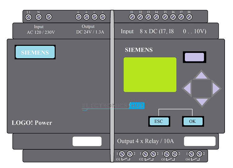
A Programmable Logic Controller (PLC) is an industrial computer that accepts real time parameters from various sensors and operates the output devices based on the logic implemented in its program. PLC replaces hardwired controlled devices like timers, relays, counters and sequencers with programmed instructions and solid state components. The below figure shows the basic hardware components of a PLC. A typical PLC system consists of components like Power Supply, CPU, Memory Unit, Programming Device, Input and Output modules.
CPU, Processor or Controller: The operations within the PLC is controlled and processed by a main Central Processing Unit (CPU). It contains arithmetic and logic unit to perform data manipulation and logical operations. The CPU reads the status of the Input Devices and executes the control program in order to control the load. Memory Unit: It stores the instructions needed to run the program, the data to be processed from input sensors and the data to be sent for output devices. It consists of ROM as a permanent storage for operating system and other data used by the CPU. RAM is used for storing the user program, status of various input and output devices and history data of various devices. Power Supply Unit: Power Supply Unit provides the necessary power to the PLC. It converts the mains AC voltage to the low DC voltage as per the requirements needed to power the processor and the other circuits in input, output and communication modules. Most PLC systems work at 230V AC or 24V DC. Input / Output Modules: Input and Output Modules form the physical connections to the field modules to the main controller. I/O modules i.e. sensors and actuators allow the PLC system to interface with the outside world. PLCs typically consists of many number of channels for input and output devices with integrated isolation and signal conditioning circuits so that each sensor and actuator can be connected directly to the PLC without any external circuitry. I/O Modules can be either fixed i.e. controller and I/O are packed together or modular i.e. I/O can be easily fitted into removable racks. The most commonly used I/O devices include Program and Programming Device: The heart of the PLC is the CPU and we need to program the CPU as per the requirement. Usually, the programming part of the PLC is implemented using a dedicated language and is generally a Graphical Method. The Program for PLC can be designed by the operating engineers without vast knowledge in computers or programming. The program must be loaded into the memory of the PLC using external programmers and the controller monitors the input and output devices according to this program. Additional Hardware: In addition to the above mentioned components, some additional components like connectors for connecting external modules (USB, RS232, SD Card, etc.), communication interface for connecting with the network (Ethernet), chassis, etc.
Basic Working of a PLC
The working of PLC can be categorized into four basic stages of operation
Initial Setup Reading data from the Inputs Executing the Instructions Commanding the Output peripherals
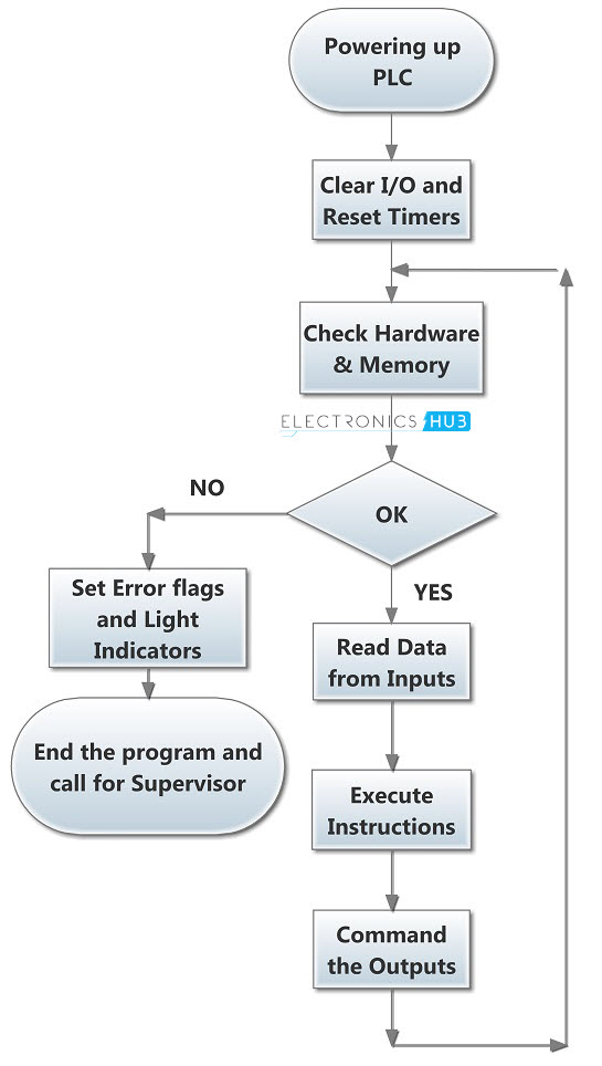
The following image shows a basic flowchart of the working of the PLC. This flow is just a typical working and doesn’t necessarily represent the actual work flow.
Whenever PLC is turned ON, it loads all the necessary instructions and functions and correspondingly checks the faults in hardware and software. This stage is called self test, during which checking for errors in all cards is performed. If there are no errors, PLC processor reads the input values from various input modules (to which various sensors are connected) and copies their values into the memory. This is called input scan stage.
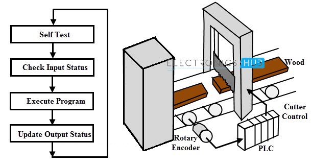
The next stage is to execute the program which is also termed as logic scan. During this, input data from memory is compared and processed by the logic program (ladder logic program or any other type of program) and correspondingly output values are updated in the temporary memory. And the final stage is the output scan during which outputs connected to the output module will be updated using the values stored in temporary memory during logic scan. Usually, this whole process repeats 10 to 100 times in a second. We will see a real time example of PLC operating in a wood cutter industry. The following figure illustrates the operation of a programmable logic controller to perform the automatic operation of wood cutter.
This system consists of a rotary encoder, cutting blade with pneumatic piston arrangement and a programmable logic controller unit. PLC is programmed in such a way that for a desired length of wooden peace, output will drive the pneumatic piston. PLC also offers to vary the program, according to the desired length of the wooden piece. It scans the input from a rotary encoder which measures moving distance of the wooden block. Based on the program, PLC compares the input data and correspondingly sends the output to the cutter.
Advantages of PLC
PLCs are built ruggedly and are used in industries where they must withstand rigorous temperatures, humidity, vibrations and other extreme operating conditions. PLCs eliminate the complex hard wiring associated with traditional relay based control systems. PLCs are fast and the response time is very less. Programmable Logic Controllers or PLCs can have a modular design and plug and play modules. The program for PLC can be easily modified and update its functionality that to rewire the relay circuits. Also the troubleshooting process for hardware and software modules in easy.
Applications of Programmable Logic Controllers (PLC)
Programmable Logic Controllers or PLCs are optimized for industrial environment in order to control processes. PLCs are used in almost all industries like automotive, chemical, food, metal, mining, power, etc. for different tasks like batch processing, material conveyors, packaging, operating cranes, waste management etc.
PLC Programming Languages
PLC programming is not very difficult compared to other computer programming languages. The major advantage of PLC is that it allows multiple languages within the same controller to program it. So the user (or program developer) has to select the best suited language to develop logic for specific application. The software model and programming languages of a PLC are dealt by IEC standard 1131-3. The five languages recommended by this standard for a PLC are discussed below.
Instruction List (IL)
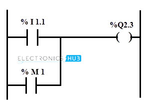
It is a low level language and it is similar to assembler language programming. IL consists of many lines of code where each line represents exactly one operation. If this program is written using IEC defined instructions, the program can be moved easily to different IEC compliant PLCs. IL is well suited for small applications which involve simple mathematical functions. This language is much more compact and requires less space in the PLC memory. However, this language is not user friendly and not very powerful. Also, implementing complex functions like PID and complex mathematical computations involves greater effort. Instruction list program for controlling the load from two sources by implementing OR logic is given below with corresponding ladder diagram. LD % I1.1 (Load input bit) OR % M1 (OR of the M1 with the result of previous result) ST %Q2.3 (Set the output bit)
Structured Text (ST)
It is a high level textual language similar to BASIC and Pascal. It can handle the complexity of program by implementing process control functions, calculus, trigonometry and data analysis far easier than ladder and IL programming. Also, it runs much faster than IL and easily gets transferable to any other IEC hardware PLCs with very few changes. Users who trained in high level text languages would be comfortable with structure text language. However, it is unsuitable for troubleshooting and somewhat unfamiliar for the service and maintenance personnel. The following is the structure text programming language for heater and cooler ON and OFF based on the temperature. IF (TEMP > 20) THEN HEATER: = OFF; COOLER: = ON; ELSIF (TEMP > 19) HEATER: = ON; COOLER: = OFF; END_IF;
Ladder Diagrams (LD)
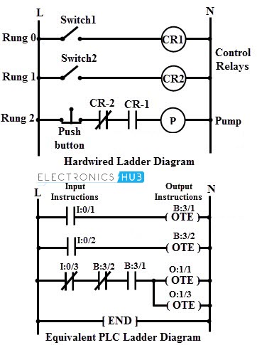
The most widely used programming language for a PLC is the ladder logic, which is invented to replace the hardwired relay control systems. It is the simple and widespread adopted language, even a non programmer with electrical background able to understand and troubleshoot the pogram. It is a graphical type of language consisting of several logic functions between rungs and power rails.
The above image shows the hardwired ladder diagram for pump control system in which horizontal lines are called as rungs while vertical two lines at rung extremities are called power rails. The left rail is the line or hot wire of the power supply while the right side rail is the neutral power rail (common terminal of power supply). In the equivalent PLC program for pump control is given below which is similar to the hardwired logic consisting of rungs and power rails. Each individual rung consists of one or more input instructions on its left-hand side and one or more output instructions on its right-hand side. In this, the input instructions Examine If open (XIO) and Examine If Closed (XIC) are analogous to relay contacts while the output instruction Output Energize (OTE) is analogous to relay coil. These output and input instructions connected with wires as shown in figure.
Function Block Diagram
It is also a graphical language and is the second most widely used programming language. It consists of various functional blocks which are reusable software elements consisting of one or more inputs and one or more outputs.
These function blocks include logic gates, counters, timers, PID, data conversion blocks, etc. However a large amount of screen space is required by this style of programming.
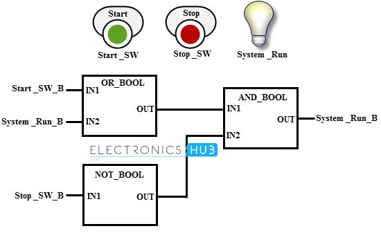
The image above shows the function block diagram of a simple lamp control unit from two input sources, i.e., from start and stop switches. Three Boolean functional blocks OR, NOT and AND are wired in this example to produce the control logic. If the start button is pressed, the output becomes true and glows the blub.
The system run output is applied at the OR Boolean function, thereby once the start button is pressed the bulb will continue to glow even if start button is OFF provided the stop button must be in OFF state as shown below.
Sequential Function Chart
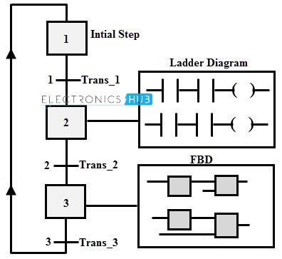
It is a graphical programming language that resembles computer flow charts. This type of program controls the system as a series of steps and transitions. It consists of action boxes, where each box can be programmed with any language that we discussed above. Each box is active until next transition step is activated. Once the current box is turned OFF, next step in the sequence is active and so on.
The figure above shows the flow chart programming of a mixing process where the process is divided into transitions. Each transition is executed sequentially before the condition for each transition is satisfied. Suppose if a stirrer tank is to be filled by two liquids up to a certain level, then mixer has to be turned ON for a several minutes and finally mixed content passed (emptying the tank) to another tank. This sequential process is executed by the below figure. Each transition can be programmed with any programming language. Comment * Name * Email * Website
Δ






![]()